Introduction to the ESP32
In my work, I am testing the ESP32 NodeMCU CP2102 dev1, which succeeds the ESP8266. Figure 1 shows this board.
Figure 1 – ESP32

The CP2102 USB-to-UART Bridge
The CP2102/9 is a highly-integrated USB-to-UART bridge controller, which provides a simple solution for updating RS-232 designs to USB using minimal components and PCB space. The CP2102/9 includes a USB 2.0 full-speed function controller, USB transceiver, oscillator, EEPROM or EPROM, and an asynchronous serial data bus.
Furthermore, free Virtual COM Port (VCP) device drivers from Silicon Laboratories allow the CP2102/9 product to appear as a COM port to PC applications.
The CP2102/9 UART interface implements all RS-232 signals, including control and handshaking signals. Consequently, you do not need to modify existing system firmware. In many existing RS-232 designs, all you need to upgrade the design from RS-232 to USB is to replace the RS232 level-translator with the CP2102/9. Additionally, Silicon Laboratories provides direct access driver support.
The ESP32-D0WD itself contains a dual-core Xtensa® 32-bit LX6 MCU.
A Deeper Look at ESP32 Components
Core Features and Power Management
Developers designed the ESP32 for mobile devices, wearable electronics, and Internet of Things (IoT) applications. It includes all the state-of-the-art features of low-power chips, such as fine-grained clock gating, multiple power modes, and dynamic power scaling.
For example, in a low-power IoT sensor hub application, the ESP32 wakes up from sleep periodically only when it detects a specific condition. Additionally, the chip uses a low duty cycle to minimize the energy it consumes. You can also adjust the power amplifier’s output, which contributes to an optimal trade-off between communication range, data rate, and power consumption.
High Integration and Manufacturing
The ESP32 is a highly integrated solution for Wi-Fi and Bluetooth IoT applications, requiring only approximately 20 external components. The ESP32 integrates an antenna switch, RF balun, power amplifier, low-noise receive amplifier, filters, and power management modules. As a result, the entire solution occupies a minimal printed circuit board (PCB) area.
Furthermore, the ESP32 uses CMOS for a single-chip fully integrated radio and baseband. It also integrates advanced calibration circuits that allow it to eliminate external circuit defects or adapt to changes in external conditions. Therefore, mass production of ESP32 solutions does not require expensive and specialized Wi-Fi testing equipment.
On-Chip Interfaces and Peripherals
The ESP32 is packed with versatile peripherals. Let’s look at the most common ones.
GPIO (General Purpose Input/Output)
The ESP32’s GPIO interface has 34 pins, which you can assign various functions by programming the corresponding registers. There are several types of GPIO, including digital-only, analog, and capacitive touch. Importantly, you can configure analog GPIOs and capacitive touch GPIOs as digital GPIOs.
UART (Universal Asynchronous Receiver-Transmitter)
The ESP32 has three UART interfaces (UART0, UART1, and UART2) that provide asynchronous communication (RS232 and RS485) and IrDA support, with data exchange at speeds up to 5 Mbps. UART also provides hardware management for CTS and RTS signals and software flow control (XON and XOFF). The DMA controller or the CPU can access all interfaces.
I2C (Inter-Integrated Circuit)
The ESP32 features two I2C bus interfaces, which can serve as an I2C master or slave depending on the user’s configuration. The I2C interfaces support standard mode (100 Kbit/s), fast mode (400 Kbit/s), and speeds up to 5 MHz (though this is limited by SDA pull-up strength), as well as 7-/10-bit addressing and dual addressing modes. This allows users to program command registers to control the I2C interfaces for greater flexibility.
I2S (Inter-IC Sound)
Two standard I2S interfaces are available in the ESP32. They can operate in master or slave mode, in full-duplex and half-duplex communication modes. You can also configure them to work with 8-, 16-, 32-, 48-, or 64-bit resolution as input or output channels. The chip supports a BCK clock frequency from 10 kHz to 40 MHz. When one or both I2S interfaces are configured in master mode, the master clock can output to an external DAC/CODEC. Finally, both I2S interfaces have dedicated DMA controllers and support PDM and BT PCM interfaces.
PWM (Pulse Width Modulation)
You can use the Pulse Width Modulation (PWM) controller to control digital motors and smart lights.
SPI (Serial Peripheral Interface)
The ESP32 has three SPIs (SPI, HSPI, and VSPI) in slave and master modes, which support 1-line full-duplex and 1/2/4-line half-duplex communication modes.
ESP32 NodeMCU Diagrams
Pin Configuration
Figure 2 shows the pin configuration.
Figure 2 – Pin configuration.

Testing ESP32 Sensor Compatibility
DHT-22 (AM2302) Temperature and Humidity Sensor
The DHT-22 (also called AM2302) uses a capacitive humidity sensor and a thermistor to measure the surrounding air.
We tested the ESP32 with the DHT22 sensor for compatibility in the Arduino environment. We transmitted data via pin 27:
C++
dht.setup(27, DHTesp::DHT22);
Adafruit PIR Motion Sensor
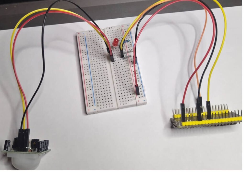
At the same time, while checking sensor compatibility with the ESP32, we connected an Adafruit PIR Motion Sensor, as shown in Figure 5.
The program’s idea is to detect motion in the environment; when the program detects motion, the LED turns on:
C++
const int led = 5;
const int motionSensor = 27;
As we can see, we connect the LED to pin 5 and the sensor to pin 27.
Next, I connected the IFTTT service. By connecting this sensor, we gained the ability to observe motion in real-time.
PIR sensors allow you to sense motion. We almost always use them to detect whether a person has moved into or out of the sensor’s range. They are small, inexpensive, low-power, easy to use, and do not wear out. For this reason, you can commonly find them in appliances and gadgets used in homes or businesses. People often call them PIR, “Passive Infrared,” “Pyroelectric,” or “IR motion” sensors.
PIRs mainly consist of a pyroelectric sensor (which you can see below as a round metal can with a rectangular crystal in the center) that can detect levels of infrared radiation. Everything emits low-level radiation, and the hotter something is, the more radiation it emits. Designers actually split the sensor in the motion detector into two halves. The reason for this is that we want to detect motion (change), not average IR levels. The two halves connect so that they cancel each other out. If one half sees more or less IR radiation than the other, the output signal will swing high or low.
Ultrasonic HC-SR04 Distance Sensor
In addition to this, we connected the ESP32 to the Ultrasonic HC-SR04 using the following pins:
C++
const int trigPin = 5;
const int echoPin = 18;
The sensor provides excellent non-contact range detection from 2 cm to 400 cm (~13 feet) with an accuracy of 3 mm. Since it operates at 5 volts, you can connect it directly to an Arduino or any other 5V logic microcontroller.
HC-SR04 Technical Specifications
- Operating Voltage: DC 5V
- Operating Current: 15 mA
- Operating Frequency: 40 kHz
- Maximum Range: 4 m
- Minimum Range: 2 cm
- Accuracy: 3 mm
- Measurement Angle: 15 degrees
- Trigger Input Signal: 10 μs TTL pulse
- Size: 45 x 20 x 15 mm
Understanding the HC-SR04 Pins
- VCC: Supplies power to the HC-SR04 ultrasonic sensor. You can connect it to the 5V output of your Arduino.
- Trigger: We use the Trigger pin to initiate the ultrasonic sound pulses. By setting this pin to HIGH for 10 μs, the sensor initiates an ultrasonic burst.
- Echo: During the transmission of the ultrasonic signal, the Echo pin goes high and stays high until the sensor receives the echo, after which it goes low. By measuring the time the Echo pin remains high, you can calculate the distance.
- GND: GND is the ground pin. Connect it to the Arduino’s ground.
How the HC-SR04 Sensor Works
It all starts when you set the trigger pin to HIGH for 10 μs. In response, the sensor transmits an ultrasonic packet of eight pulses at 40 kHz. Designers specifically designed this 8-pulse pattern so the receiver can distinguish the transmitted pulses from ambient ultrasonic noise.
These eight ultrasonic pulses travel through the air from the transmitter. Meanwhile, the echo pin goes high to initiate the return echo signal.
If these pulses do not reflect back, the echo signal times out and goes low after 38 ms (38 milliseconds). Thus, a 38 ms pulse indicates no obstruction within the sensor’s range.
However, if these pulses do reflect back, the echo pin goes low as soon as the sensor receives the signal. This generates a pulse on the echo pin, the width of which varies from 150 μs to 25 ms, depending on the time required to receive the signal.
Capacitive Soil Moisture Sensor
Figure 3 – Connection diagram for the soil moisture sensor

You set the moisture measurement pin as follows:
C++
const int sensor_pin = A0;
Therefore, using the application, we can view the soil moisture from a mobile phone in real-time.
BMP280 Barometric Pressure Sensor
Finally, we tested the ESP32 for compatibility with the BMP280. The result of the program execution is in Figure 4.
Figure 4

In this case, we checked for the sensor’s presence:
C++
if (!bmp.begin(0x77)) {
  Serial.println("Could not find a valid BMP280 sensor, check wiring!");
}
We also created a web server and made the connection via the I2C protocol.