When studying discrete mathematics and computer science, mastering Boolean algebra truth tables is the absolute first step toward understanding how digital systems process information. Before computers could render photorealistic 3D graphics, route global internet traffic, or execute cryptographic algorithms like AES, they had to learn how to think. But computers do not think in English, Ukrainian, or traditional mathematics; they think purely in terms of physical electrical states: on and off, high voltage and low voltage, true and false.
This binary perception of the universe is governed by a brilliant mathematical framework. To visualize, debug, and solve problems within this framework, we rely heavily on Boolean algebra truth tables. Named after the 19th-century English mathematician George Boole, who introduced the concept in his 1854 book “The Laws of Thought”, this algebra is the bedrock of all modern digital electronics. Decades later, Claude Shannon proved that Boole’s logical equations could be perfectly mapped to electrical relay circuits, birthing the information age.
In this comprehensive, deep-dive guide, we will explore the fundamental variables of this mathematical system, dissect the basic logical operations with real-world applications, and teach you how to systematically construct Boolean algebra truth tables to evaluate complex logical statements without making analytical mistakes.
1. The Binary Universe: Boolean Variables
In traditional elementary algebra, a variable like $x$ or $y$ can represent an infinite spectrum of numbers (fractions, negative numbers, decimals). Boolean algebra is fundamentally different. It is a system of absolute certainty with no gray areas. This strict duality is exactly why Boolean algebra truth tables are so incredibly effective: there is only a finite, highly predictable number of possibilities to calculate.
A Boolean variable can only hold one of two possible values:
- 1 (True): In hardware, this represents a closed circuit, a high electrical signal (typically 5V or 3.3V in logic boards), or a logically valid condition in software.
- 0 (False): Representing an open circuit, a grounded signal (0V), or a logically invalid condition.
Because a transistor inside a modern CPU acts simply as a switch that is either conducting (1) or blocking (0) electricity, we can exhaustively map out the behavior of any logical function. A Boolean function simply takes these binary inputs, processes them through physical or software “logic gates,” and spits out a single deterministic binary output.
2. The Core Logical Operations: Theory & Practical Application
Just as traditional arithmetic has addition and multiplication, this system utilizes a specific set of logical operators. Let’s break down the foundational operations you will use when building your Boolean algebra truth tables, and examine how they are actually used in the real world.
A. Logical Negation (NOT / Inversion)
The simplest operation is negation, often denoted by the symbol $\neg$, a tilde $\sim$, or an overline ($\bar{x}$). It is a unary operator, meaning it requires only a single variable.
The Rule: It acts as a mirror, flipping the value to its absolute opposite.
- If $x = 1$, then $\neg x = 0$.
- If $x = 0$, then $\neg x = 1$.
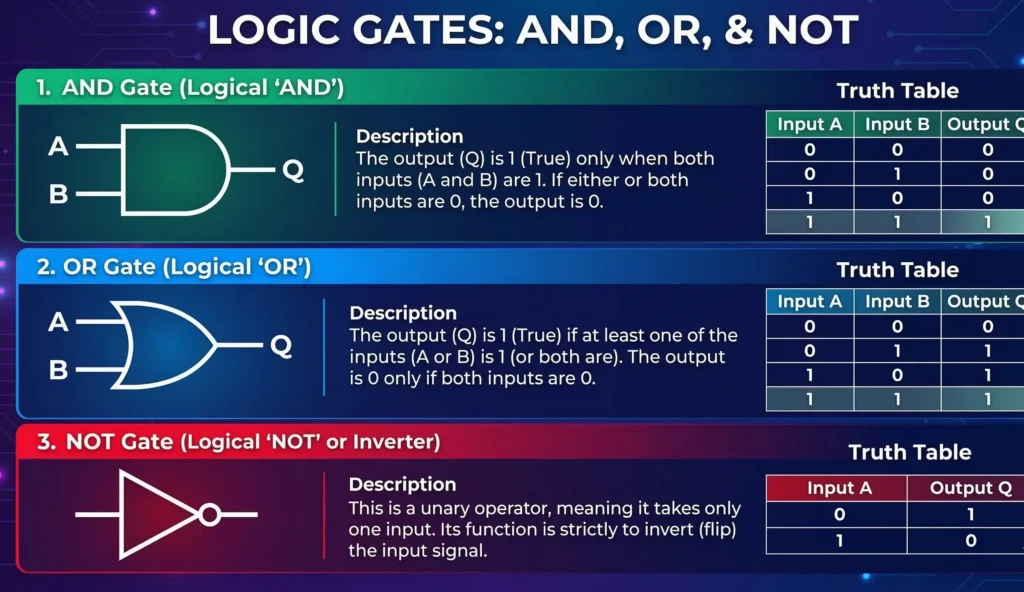
Practical Application: Fail-safe mechanisms and inverters. Imagine a factory machine with an emergency stop button. The machine should run (1) when the button is NOT pressed (0). If the button is pressed (1), the inverted logic sends a (0) to the motor, safely stopping it.
B. Logical Conjunction (AND / Multiplication)
Conjunction is the logical equivalent of multiplication. It is denoted by the wedge symbol $\land$, an ampersand $\&$, or sometimes simply written as a product ($xy$).
The Rule: The output is 1 only if all inputs are 1. If even a single input is 0, the entire statement collapses to 0.
- 0 $\land$ 0 = 0
- 0 $\land$ 1 = 0
- 1 $\land$ 0 = 0
- 1 $\land$ 1 = 1
Practical Application: Security authentication. To log into your bank account, the system checks: Password is correct (1) AND 2FA token is correct (1). Both conditions must be simultaneously true to grant access. If either fails, access is 0.
C. Logical Disjunction (OR / Addition)
Disjunction is the logical equivalent of addition. It is denoted by the vee symbol $\lor$, or a plus sign $+$. Note that this is an “inclusive OR.”
The Rule: The output is 0 only if both inputs are 0. If at least one input is 1, the entire statement becomes 1.
- 0 $\lor$ 0 = 0
- 0 $\lor$ 1 = 1
- 1 $\lor$ 0 = 1
- 1 $\lor$ 1 = 1
Practical Application: Sensor networks and alarms. A smart home alarm system will trigger (1) if the front door opens (1) OR if a window breaks (1). Either single event, or both happening together, is enough to activate the siren.
D. Exclusive OR (XOR / Modulo-2 Addition)
The Exclusive OR is perhaps the most important gate in computer science, specifically in arithmetic and cybersecurity. It is denoted by a circled plus sign $\oplus$.
The Rule: The output is 1 if the inputs are strictly different, and 0 if the inputs are the same.
- 0 $\oplus$ 0 = 0 (Same = 0)
- 0 $\oplus$ 1 = 1 (Different = 1)
- 1 $\oplus$ 0 = 1 (Different = 1)
- 1 $\oplus$ 1 = 0 (Same = 0)
Practical Application: Cryptography. XOR is the mathematical heart of ciphers like the One-Time Pad and AES. If you XOR a piece of data with a random key, it scrambles it completely. If you XOR it with that exact same key a second time, the original data is magically restored (since $A \oplus K \oplus K = A$).
E. Logical Implication (Conditional)
Implication is denoted by an arrow $\to$ and represents an “If… then…” statement. It evaluates the relationship between a premise ($x$) and a conclusion ($y$).
The Rule: The output is 0 only if a true premise leads to a false conclusion (1 $\to$ 0 = 0). All other combinations logically evaluate to 1.
- 1 $\to$ 1 = 1 (True premise leads to True conclusion. Valid.)
- 1 $\to$ 0 = 0 (True premise leads to False conclusion. Invalid.)
- 0 $\to$ 1 = 1 (False premise. The conditional promise wasn’t triggered, so it technically isn’t broken. Valid.)
- 0 $\to$ 0 = 1 (False premise. Valid.)
Practical Application: Rule-based AI and database triggers. “IF an employee has worked > 5 years, THEN they get a bonus.” If someone worked 6 years (1) but got no bonus (0), the company violated the rule (returns 0). If they worked 2 years (0), the rule isn’t violated regardless of whether a bonus was given or not.
3. The Architecture of Boolean Algebra Truth Tables
The true power of Boolean algebra truth tables lies in their structural predictability. A truth table is a mathematical matrix that systematically lists all possible combinations of input variables, ensuring absolutely no edge cases are missed.
Because each variable can only hold 2 values (0 or 1), a function with $n$ variables will always require exactly $2^n$ rows in your Boolean algebra truth tables.
- 1 variable ($x$): $2^1 = 2$ rows.
- 2 variables ($x, y$): $2^2 = 4$ rows.
- 3 variables ($x, y, z$): $2^3 = 8$ rows.
- 4 variables ($w, x, y, z$): $2^4 = 16$ rows.
How to Systematically Fill the Rows
To avoid missing any combinations, you must write the input rows by counting in standard binary logic from 0 upwards. For 3 variables ($x, y, z$), you count from 0 to 7 in binary:
- 000
- 001
- 010
- 011
- 100
- …and so on up to 111.
4. Step-by-Step Example: Evaluating a Complex Function
Let’s put theory into practice by solving a real university-level discrete mathematics problem using Boolean algebra truth tables. We will evaluate the following function containing three variables ($x$, $y$, and $z$), a negation, and two implications:
$$f(x, y, z) = \neg x \to (z \to y)$$
Setting up the Matrix & Analytical Breakdown
Since we have 3 variables, we need 8 rows. We do not jump straight to the answer. We follow the order of operations (similar to PEMDAS in standard math), creating intermediate columns to avoid human error.
- Inner parentheses first: We create a column for $(z \to y)$. We look at $z$ and $y$. It will only be 0 when $z=1$ and $y=0$.
- Negations next: We create a column for $\neg x$, completely flipping the $x$ column.
- Final resolution: We evaluate the main implication arrow by treating $\neg x$ as our premise (left side) and $(z \to y)$ as our conclusion (right side).
| $x$ | $y$ | $z$ | Inner: $(z \to y)$ | Left: $\neg x$ | Final: $f = \neg x \to (z \to y)$ |
|---|---|---|---|---|---|
| 0 | 0 | 0 | 1 | 1 | 1 |
| 0 | 0 | 1 | 0 | 1 | 0 |
| 0 | 1 | 0 | 1 | 1 | 1 |
| 0 | 1 | 1 | 1 | 1 | 1 |
| 1 | 0 | 0 | 1 | 0 | 1 |
| 1 | 0 | 1 | 0 | 0 | 1 |
| 1 | 1 | 0 | 1 | 0 | 1 |
| 1 | 1 | 1 | 1 | 0 | 1 |
Analysis of the Final Result: Look at the final green column. The function outputs 1 for almost every combination, except for the single case in Row 2 where $x=0, y=0$, and $z=1$. In that specific scenario, the left side of our main implication ($\neg x$) evaluated to 1, while the right side ($z \to y$) evaluated to 0. Since 1 $\to$ 0 is the only way to break an implication rule, the entire function collapsed to 0.
Conclusion: Why Do We Need Boolean Algebra Truth Tables?
By breaking down highly complex logical statements into manageable columns, Boolean algebra truth tables completely eliminate guesswork. Beyond passing academic discrete math exams, these matrices form the foundation of real-world hardware and software design.
Whenever hardware engineers create the logic units (ALU) inside computer CPUs, they use Boolean algebra truth tables to verify that their logic gates will behave predictably under every possible input. Similarly, software developers subconsciously use this logic every day to debug complex nested `if-else` programming conditions or optimize SQL database queries.
In our next module, we will explore advanced logical evaluation techniques. We will dive into the Zhegalkin Polynomial to understand Boolean linearity, and eventually move to Karnaugh Maps to learn the art of visual logic minimization (shrinking giant equations into highly efficient circuits).
Bądź na bieżąco!
Zapisz się, aby nie przegapić nowości na Review Space.
Join Our Newsletter
No spam. Unsubscribe anytime.