The Arduino Uno stands as a cornerstone of the maker movement, a powerful yet accessible tool for everyone from hobbyists to professional engineers. But what exactly makes it tick? This article takes a deep dive into the core components of the Arduino Uno, from its microcontroller brain to the essential communication protocols that enable it to interact with the outside world.
Understanding the Arduino Uno Board
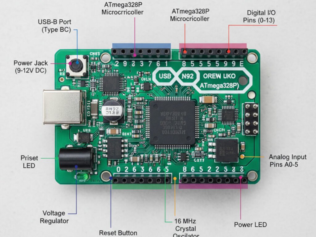
The Arduino Uno is a popular microcontroller board that utilizes the ATmega328P. It comes equipped with 14 digital input/output pins (6 of which offer PWM outputs), 6 analog inputs, a 16 MHz ceramic resonator, a USB connection, a power jack, an ICSP header, and a reset button.
The name “Uno,” meaning “one” in Italian, was chosen to mark the release of the Arduino Software (IDE) 1.0. Both the Uno board and version 1.0 of the Arduino IDE served as the original reference versions of Arduino, paving the way for newer iterations. As the first in a series of USB Arduino boards, the Uno remains a foundational model for the entire Arduino platform.
The Heart of the Uno: The ATmega328P Microcontroller
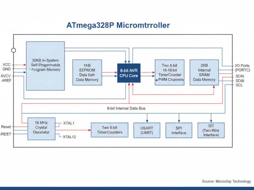
At its very core, the Uno features the ATmega328P, a high-performance, low-power 8-bit AVR® RISC-based microcontroller. This powerful chip boasts 131 instructions, most of which execute in a single clock cycle. Consequently, it achieves a throughput of up to 16 MIPS at 16 MHz.
Key Memory Specifications
To effectively run your projects, the ATmega328P includes various types of memory:
- 32 KB of Flash memory stores your program code permanently.
- 1 KB EEPROM offers non-volatile storage for data that needs to persist even after power loss.
- 2 KB of internal SRAM provides volatile memory for variables during runtime.
Furthermore, it integrates a rich set of peripheral features. These include two 8-bit timers, one 16-bit timer, six PWM channels, an 8-channel 10-bit ADC (found in TQFP and QFN/MLF packages), a programmable serial USART, an SPI serial interface, and an I2C-compatible 2-wire serial interface.
Persistent Memory: Exploring EEPROM
Imagine connecting an LED to your breadboard. When you press a switch, the LED lights up. However, if the power is lost, the Arduino reboots, and the LED turns off. Its previous “on” state is gone.
If you want the Arduino to remember its last state, you need persistent memory. This is precisely where EEPROM (Electrically Erasable Programmable Read-Only Memory) becomes invaluable.
You can write the LED’s previous state directly to the EEPROM. Then, upon Arduino startup, you can simply check this stored value to restore the previous state.
Essential EEPROM Functions
Working with EEPROM typically involves these key functions:
EEPROM.write(address, value): Stores a value at a specific address.EEPROM.read(address): Retrieves a value from a specific address.EEPROM.update(address, value): Writes a value only if it differs from the current value at the address, extending EEPROM lifespan.
EEPROM Lifespan Considerations
It’s important to note that EEPROM has a limited lifespan. For Arduino, the EEPROM supports 100,000 write/erase cycles for each position. Conversely, the number of reads is unlimited.
The underlying technology behind EEPROM places limits on how many times it can be rewritten. This occurs because electrons become trapped in the transistors that form the ROM, accumulating until the charge difference between a “1” and a “0” becomes indistinguishable. While most EEPROMs can handle 1 million or more rewrites, you are unlikely to reach this limit unless you are constantly writing to the EEPROM.
Additionally, while the EEPROM retains data when power is off, it doesn’t store data indefinitely. Electrons can slowly drift from the transistors, gradually erasing the EEPROM over time. This process generally takes many years, though heat can accelerate it. Most manufacturers typically claim data stored in EEPROM remains intact for 10 years or more at room temperature.
Understanding Arduino Communication Protocols
The Arduino’s true power lies in its ability to interact with a wide range of sensors, modules, and other computers. It achieves this through standardized communication protocols, each serving distinct purposes.
1. UART (Universal Asynchronous Receiver/Transmitter)
The UART peripheral is an industrial-standard communication element that can be switched into an alternative FIFO (First-In, First-Out) mode. This frees the CPU from excessive software overhead by buffering received and transmitted characters. The receiver and transmitter FIFOs store up to 16 bytes each.
UART performs:
- Serial-to-parallel conversions on data received from a peripheral.
- Parallel-to-serial conversions on data received from the CPU.
The UART includes a programmable baud rate generator capable of dividing the input clock signal to produce a reference clock for the transmitter and receiver logic.
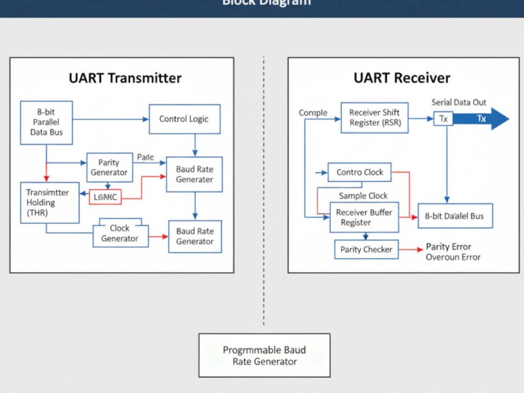
The UART transmitter section includes a transmitter holding register (THR) and a transmitter shift register (TSR). The receiver section includes a receiver shift register (RSR) and a receiver buffer register (RBR).
Based on settings in the Line Control Register (LCR), the UART transmits in this format:
- 1 start bit
- 5, 6, 7, or 8 data bits
- 1 parity bit (optional)
- 1, 1.5, or 2 stop bits
It receives in a similar format:
- 1 start bit
- 5, 6, 7, or 8 data bits
- 1 parity bit (optional)
- 1 stop bit
2. I2C (Inter-Integrated Circuit)
The I2C bus transmits data and clock signals using two lines: SDA (Serial Data) and SCL (Serial Clock).
A key feature of I2C is that the devices (both masters and slaves) have an open-drain (or open-collector) configuration. This means they can only pull the lines LOW or leave them “open” (high-impedance). A pull-up resistor (Rp) is required to pull the line HIGH (to Vcc) when no device is pulling it low.
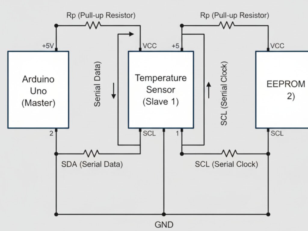
This design allows for features like multi-master operation and clock stretching (where a slave can slow down communication by holding SCL low). This is also the reason for the characteristic “sawtooth” appearance of I2C signals, showing the charge/discharge characteristics of the line.
To prevent address conflicts within the limited 7-bit range, a new 10-bit addressing scheme was introduced. This scheme is initiated by the master sending “11110” after the start condition. Devices that only use 7-bit addressing will simply ignore this message.
3. SPI (Serial Peripheral Interface)
SPI is a “synchronous” data bus, meaning it uses separate lines for data and a clock (CLK or SCK), which keeps both sides in perfect synchronization. The clock is an oscillating signal that tells the receiver exactly when to sample the bits on the data line.
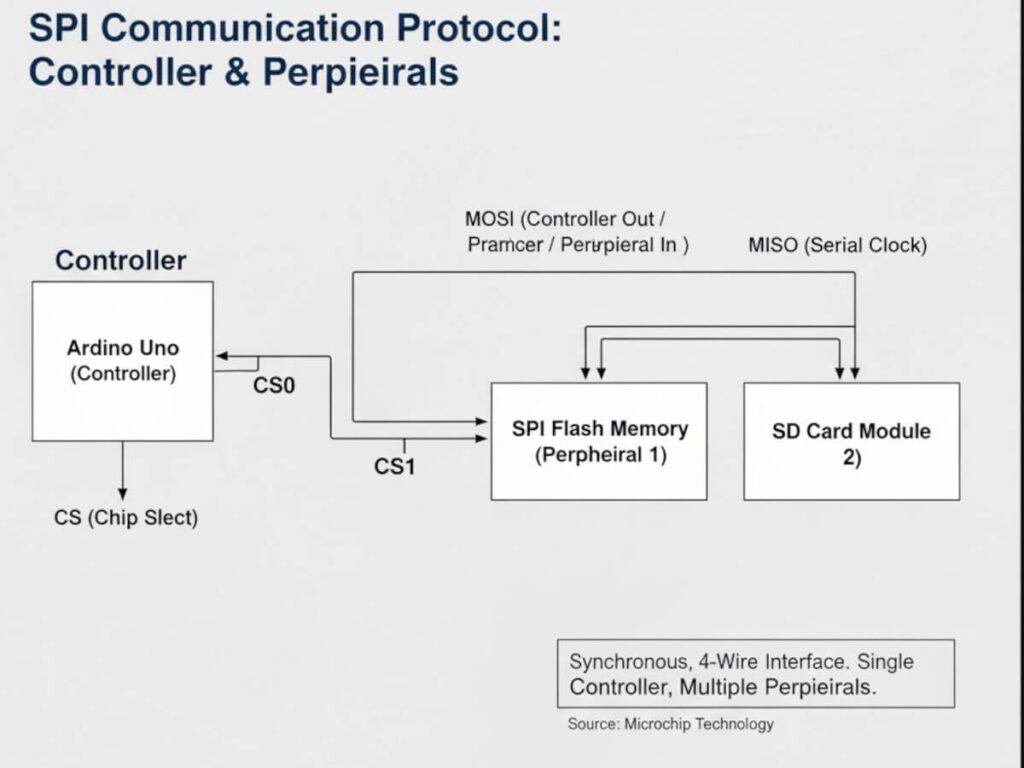
- Controller and Peripheral: In SPI, only one side generates the clock signal. This side is called the “controller” (almost always your microcontroller). The other side is the “peripheral.”
- Data Lines:
- PICO (Peripheral-In / Controller-Out): Data from the controller to the peripheral. (Also commonly known as MOSI – Master Out Slave In).
- POCI (Peripheral-Out / Controller-In): Data from the peripheral back to the controller. (Also commonly known as MISO – Master In Slave Out).
- Chip Select (CS): This line tells the peripheral to “wake up” and receive/send data. It is used to select which peripheral the controller wants to communicate with when multiple are present.
In Arduino, you can use software commands like shiftIn() and shiftOut(), which work on any group of pins but are slow. It is much better to use the SPI library, which utilizes the dedicated SPI hardware built into the microcontroller. This is much faster but only works on specific pins (SCK, PICO, POCI).
Pin Configuration and Schematics
Pin Configuration
Each of the 14 digital pins on the Uno can be used as an input or output using the pinMode(), digitalWrite(), and digitalRead() functions. They operate at 5 volts. A critical limit is 40 mA, which should not be exceeded on any I/O pin to avoid permanent damage to the microcontroller.
The Arduino Uno board can be powered via the USB connection or from an external power supply, which is selected automatically.
Arduino Uno Schematics and Power
External (non-USB) power can come from an AC-to-DC adapter or a battery. The board can operate on an external supply of 6 to 20 volts.
- If supplied with less than 7V, the 5V pin may supply less than five volts, and the board may become unstable.
- If using more than 12V, the voltage regulator may overheat and damage the board.
- The recommended range is 7 to 12 volts.
The Vin pin is the input voltage to the Arduino board when it’s using an external power source. You can supply voltage through this pin, or, if supplying voltage via the power jack, access it through this pin.
Atmega168 Pinout: A Detailed Look
The diagram below illustrates the pinout for the DIP package of the Atmega168. (Note: The Atmega168 is a predecessor to the ATmega328P, sharing a very similar pinout). On the right side, pins PC0-PC5 are clearly marked as ADC (Analog-to-Digital). This means these pins can read an analog signal ranging from 0 to 5V when you use the analogRead() function.
The Atmega168 features two digital supply voltage pins: VCC and AVCC. AVCC specifically supplies power to pins PC0-PC5. When you use these pins as analog inputs, the AVCC power supply must be exceptionally stable, which engineers often achieve by incorporating a low-pass filter (typically an inductor and capacitor).
Practical Tests: Verifying Sensor Compatibility
Theory is undeniably valuable, but seeing it in action provides crucial validation. Therefore, we conducted practical tests to confirm the Arduino Uno’s compatibility with two commonly used sensors.
1. BMP280 Barometric Pressure Sensor Integration
The BMP280 barometric pressure sensor is versatile, supporting both I²C and SPI digital interfaces. Its I²C interface further supports Standard, Fast, and High-Speed modes. For our test, we integrated a BMP280 sensor using the I2C interface, which had an address of 0x77.
We ran the test using the I2C interface and successfully obtained readings for temperature, pressure, and even an approximate altitude calculation. The Arduino Uno seamlessly communicated with the sensor, demonstrating its capability.
2. Adafruit UV TCS34725 Color Sensor Integration
Next, we tested the Adafruit UV TCS34725 color sensor. This particular sensor module is highly convenient, as it includes auxiliary circuits such as a 3.3V regulator (allowing safe powering with 3-5V DC) and level shifting for the I2C pins (making it compatible with both 3.3V and 5V logic).
When we executed the program, the connected RGB LED dynamically changed its color based on the color detected by the sensor. This visually confirmed the Arduino Uno’s successful interaction and data processing from the TCS34725.
Conclusion
In this article, we thoroughly examined the core features of the Arduino microcontroller and extensively explored the communication protocols that are fundamental to any platform’s interaction with sensors and other devices.
Ultimately, we conclude that the Arduino platform stands out as one of the simplest, easiest to program, and simultaneously most powerful systems available. This controller is distinguished by its remarkable stability, resilience, and simplicity, all while delivering powerful capabilities.
It’s remarkably straightforward to connect a Wi-Fi module or a Bluetooth module to the Arduino Uno. This immediately opens up possibilities for communicating with other controllers, managing sensors over the internet, or even via Bluetooth. Such flexibility allows for the creation of full-fledged web applications and seamlessly integrates this classic controller into modern Internet of Things (IoT) projects.