Ever wondered what it takes to build a “smart home” from scratch? It’s not just about buying off-the-shelf gadgets. In this guide, I’ll walk you through three practical, hands-on IoT projects I developed, covering everything from a custom-built API to an automated plant-watering system and a fingerprint-controlled door lock. We’ll explore the hardware, the software, and the key components that bring these ideas to life.
🌡️ Project 1: A Custom Temperature & Humidity Monitoring API
Our first project was to develop a web API using the Flask framework to monitor room temperature and humidity. The goal was to get data from a sensor and display it on a web page accessible from anywhere.
⚙️ The Tech Stack
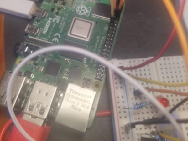
- Hardware: Raspberry Pi (running Raspbian Lite) and an AM2302 sensor connected to GPIO17.
- Software: Python, Flask (as the web framework), NGINX (as the web server), uWSGI (to connect NGINX and Flask), and an SQLite3 database to store the readings.
📈 How It Works: From Sensor to Screen
A cron job automates the process, taking a reading from the sensor every 10 minutes and saving it to the database. The web page itself is dynamic, refreshing every 10 seconds to show the most current data. By setting up port forwarding, the server is accessible over the internet, allowing us to check the temperature from anywhere.
📦 Key Challenge: Taming Python with Virtual Environments
Python development can be tricky as libraries and applications are constantly changing. The solution was using a venv (virtual environment). This isolates the project’s dependencies, ensuring the application remains stable and testable, even as system-wide packages are updated. We created it using the command: python -m venv tutorial-env.
💧 Project 2: An Automated Plant Watering System
The second project is an automated watering system, perfect for keeping plants alive! This system was built using Node-RED hosted on a Raspberry Pi.
🤖 How It Works: Node-RED, MQTT, and Google Sheets
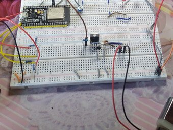
The system uses two main circuits: one for the soil moisture sensor (running at 3.3V) and one for the water pump (running at 5V). We used MQTT (with a Mosquitto broker) for messaging and communication.
For detailed monitoring, the system logs data to a Google Sheet every minute. This required setting up a Google Cloud project, enabling the Google Sheets and Drive APIs, and using JSON keys for authentication.
⚡ The Key Component: The TIP122 Darlington Transistor
A major challenge was controlling the 5V pump (a “high-power” device) using a low-power signal from the Raspberry Pi’s GPIO pin. The solution is a TIP122 NPN Darlington Transistor.
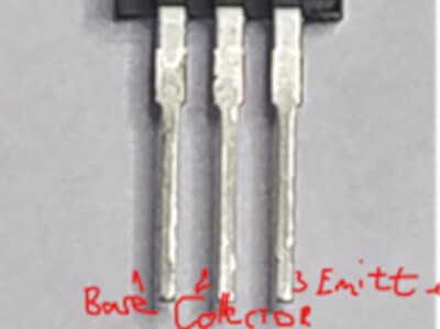
A Darlington transistor acts like a high-gain amplifier. It allows a very small current from the microcontroller to control a much larger current needed to run the motor/pump. Its high gain (around 1000) and ability to handle up to 5A make it ideal for high loads.
We also used a 1N4007 diode to protect the circuit from voltage spikes when the pump turns off. The system, using a Task Scheduler, is set to turn on the pump for 5 seconds when the soil moisture (simulated with a potentiometer) goes above a certain threshold (e.g., 550).
🔒 Project 3: Arduino Fingerprint Solenoid Lock
Finally, we built a security subsystem: a door lock controlled by a fingerprint sensor connected to an Arduino Uno. The system is designed to open the lock only if the fingerprint is recognized in its database.
Ever wanted to build your own high-tech security? In this project, we’re diving into one of the most popular smart home features: a fingerprint-controlled door lock. We’ll connect a fingerprint sensor to an Arduino Uno. The goal is simple: if your fingerprint is in the database, the lock opens. If not, it stays shut.
🛠️ The Key Components
- Arduino Uno: The brain of our operation.
- R307 Fingerprint Sensor: The biometric scanner that reads and verifies prints.
- Solenoid Lock (9V or 12V): The physical lock mechanism.
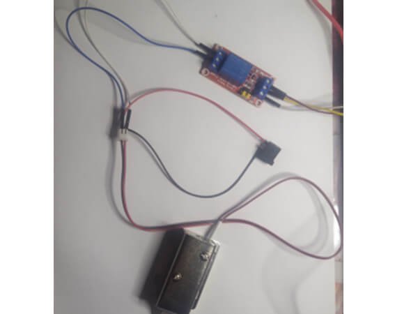
- 5V Relay Module: The critical “bridge” that lets our low-power Arduino control the high-power lock.
Part 1: Setting Up the R307 Fingerprint Sensor
The star of the show is the R307 fingerprint sensor. Getting it wired up is straightforward: connect it to the 3.3V power, Ground, and two digital pins (e.g., pins 2 and 3) on the Arduino.
For the software, we use the fantastic Adafruit_fingerprint library. The process has two steps:
- Enroll Prints: First, you’ll run the “enroll” sketch from the library. This program will guide you (via the Serial Monitor) to scan a finger, scan it again for verification, and then assign it an ID. The sensor can typically store up to 127 different fingerprints!
- Run the Lock Sketch: Once your fingerprints are saved, you’ll load the main “fingerprint” sketch. This code continuously scans for a finger. When it gets a match against its saved database, it sends a “success” signal to the Arduino, which will then trigger our lock.
Part 2: The Bridge: Why You Need a 5V Relay Module
Here’s our first big challenge: The Arduino outputs a tiny 5V signal. Our electric door lock (a solenoid) needs much more power—typically 9V or 12V.
You cannot connect the lock directly to the Arduino; you will fry the board.
The solution is a 5V relay module. Think of a relay as an electrically controlled switch. Your Arduino sends a low-power 5V signal to the relay. This signal activates a small electromagnet inside the relay, which then closes a separate, high-power switch. This second switch is what safely completes the 9V or 12V circuit and powers the lock.
A relay module is perfect for this. It has the relay, a protective diode, a transistor, and status LEDs all on one convenient board.
Part 3: How to Wire the Relay
Wiring the relay module is simple and has two parts:
1. Input Side (to the Arduino)
This side connects to your microcontroller:
- VCC: Connects to 5V on the Arduino.
- GND: Connects to GND on the Arduino.
- IN (or IN1): Connects to your chosen digital output pin on the Arduino (the one you’ll set to
HIGHto unlock).
2. Output Side (to the Lock & Power)
This side acts just like a light switch in the middle of your lock’s power wire. It has three terminals:
- COM (Common): This is the “common” connection. Connect this to the positive (+) wire from your 9V/12V power supply.
- NO (Normally Open): This is the connection that is “off” by default. Connect this to the positive (+) wire of your solenoid lock.
- NC (Normally Closed): This connection is “on” by default. We won’t use it for this project.
The negative (-) wire from your solenoid lock connects directly to the ground (-) terminal of your 9V/12V power supply.
🤝 How It All Works Together
- The Arduino waits for the fingerprint sensor.
- You place your finger on the sensor.
- The sensor finds a match and tells the Arduino.
- The Arduino sets its digital output pin (connected to
IN) toHIGH. - This
HIGHsignal activates the relay, which “clicks” and connects theCOMandNOterminals. - This completes the 12V circuit, sending power to the solenoid lock and… clack… the door unlocks!
- Your code then tells the Arduino to set the pin back to
LOW, which deactivates the relay, cuts the 12V power, and the lock re-engages.
This same 5V relay setup isn’t just for Arduinos. It can also be easily connected to a Raspberry Pi to control high-power loads like lights, motors, or fans, making it one of the most versatile tools in any DIY electronics project.
🧠 Geek-Out Corner: How the Fingerprint Sensor Really Works
Curious about what’s happening under the hood? The R307 sensor is a sophisticated piece of kit. It doesn’t just store a picture of your fingerprint. Here’s a quick look at its internal memory:
- Image Buffer: A temporary RAM buffer that holds the raw 256×288 pixel image just as you place your finger on the sensor. Its contents are lost when power is off.
- Character File Buffers (CharBuffer1 & CharBuffer2): The sensor processes the raw, high-contrast image, finds all the unique features (minutiae), and creates a “character file.” It does this twice for verification.
- Template File: It then combines these two character files to create a “template,” which is the final, processed version of your print. This template is what gets saved.
- Fingerprint Library: This is the non-volatile flash memory (it’s not erased when the power is off) where up to 1000 of these templates can be stored.
- Security Level (1-5): You can even set the security level! A low level (like 1) is faster but has a higher False Acceptance Rate (FAR). A high level (like 5) is very secure (low FAR) but might have a higher False Recognition Rate (FRR), meaning it might fail to recognize your own finger. It’s all about finding the right balance!
✅ Conclusion
As we’ve seen, these three projects (the API, the watering system, and the smart lock) were successfully designed and implemented. Each one solved a unique challenge, from software stability with virtual environments to hardware control with Darlington transistors and relay modules. This demonstrates how a “smart home” can be built with practical, efficient subsystems. We believe the goals of this project have been fully achieved.
📚 References & Further Reading
- https://hum-systems.com/en/blog/what-does-real-smart-living-mean/
- https://projecthub.arduino.cc/Shubhamkumar97/2fd190cc-51ca-47e0-afd7-c2e6dd56ff61
- https://www.mdpi.com/2673-4052/3/4/29
- https://www.academia.edu/67922510/IoT_Smart_Home_Lighting_System_using_Arduino_UNO_and_ESP8266
- https://utc.org/wp-content/uploads/2019/03/Cutting_through_the_Hype_Utilities_5G-2.pdf
- http://ww1.microchip.com/downloads/en/DeviceDoc/Atmel-7810-Automotive-Microcontrollers-ATmega328P_Datasheet.pdf
- https://store.arduino.cc/products/arduino-uno-rev3
- https://docs.arduino.cc/learn/built-in-libraries/eeprom
- https://www.ti.com/lit/ug/sprugp1/sprugp1.pdf
- https://www.i2c-bus.org/i2c-primer/typical-i2c-bus-setup/
- https://learn.sparkfun.com/tutorials/serial-peripheral-interface-spi/all
- https://www.ti.com/lit/ug/sprugp2a/sprugp2a.pdf
- https://cdn-shop.adafruit.com/datasheets/BST-BMP280-DS001-11.pdf
- https://www.electronicdesign.com/industrial-automation/article/21808300/how-to-pick-the-best-bluetooth-protocol-for-your-application
- https://www.silabs.com/documents/public/data-sheets/CP2102-9.pdf
- http://www.ocfreaks.com/basics-interfacing-dht11-dht22-humidity-temperature-sensor-mcu/amp Examples
- https://learn.adafruit.com/pir-passive-infrared-proximity-motion-sensor/overview
- https://projecthub.arduino.cc/Isaac100/getting-started-with-the-hc-sr04-ultrasonic-sensor-7cabe1
- https://www.raspberrypi.com/documentation/
- https://www.theengineeringprojects.com/2020/07/introduction-to-tip122.html
- https://www.elprocus.com/5v-relay-module/
- https://www.techtarget.com/iotagenda/definition/smart-home-or-building
- https://learn.sparkfun.com/tutorials/reading-and-writing-serial-eeproms/introduction
- https://learn.sparkfun.com/tutorials/reading-and-writing-serial-eeproms/eeprom-basics
Bądź na bieżąco!
Zapisz się, aby nie przegapić nowości na Review Space.
Join Our Newsletter
No spam. Unsubscribe anytime.